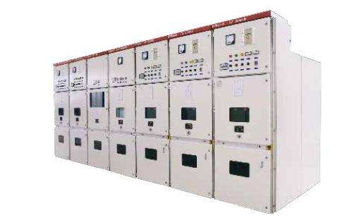
GCK low-voltage pull out type distribution cabinet is suitable for ac 50Hz, 660V and below three-phase five-wire transmission and distribution system.
As a power system for power plants, substations, industrial and mining enterprises and high-rise buildings in the use of electricity, feed, lighting and motor control.
The product conforms to IEC439-1 “low-voltage switchgear and control equipment”; Gb7251.1-1997, ZBK36001-89 “low voltage withdrawl type complete switch equipment” standard.
GCK low voltage extraction type distribution cabinet, using advanced assembly structure and combination unit, extraction combination unit IP30, safe, reliable, compact.
GCK low-voltage power distribution cabinet has a special metering cabinet, which can meet the requirements of the power supply system for low-voltage metering.
GCK low voltage power distribution cabinet, with a special electrostatic capacitor cabinet, as reactive power compensation.
Normal service conditions:
1, the ambient air temperature is not high dry +40℃, not lower than -5℃, and the average temperature within 24 hours is not higher than
℃.
2, the air is clean, relative humidity in the maximum temperature +40℃, not more than 50%; At lower temperatures, allow
For example: 90% at +20℃; Allow condensation that may occur due to changes in temperature.
3. The altitude shall not exceed 2000m.
Structure features:
GCKl low voltage withdraw power distribution cabinet is a fully assembled combination structure, and the basic skeleton is assembled with special profiles
E = 20 mm.
Because all the structures of the frame are connected by screws, welding deformation and stress are avoided, and the accuracy is improved
Each cabinet is divided into three parts, that is, the main bus room at the top which can be penetrated by the horizontal bus, the front part is divided into several functional unit chambers with a partition board, and the height after combination is 1760mm. The back part is the cable room, and the interior is equipped with a support for laying in and out cables.
A vertical bus is arranged at the back of the chamber of the extraction type functional unit, and the vertical bus is connected with the branch bus and the horizontal bus. Each extraction type functional unit is connected with the vertical bus at the connected position, and the metal sealing plate of the cabinet top is provided with a ventilation window; When the top needs to be in and out of the wire, the insulation sealing plate is used, and the bottom is the metal sealing plate, and the punching hole is punched on it to facilitate the entry and exit of the cable.
Pull-out system structure:
Electrical components of each functional unit are installed on a drawer, which can make the whole unit out of the cabinet, safe and convenient for maintenance.
The drawer is installed in a 600mm wide cabinet with three positions: “separate”, “test” and “connected”.
The inlet side of the power supply in the drawer compartment is equipped with a valve. The valve opens automatically when the drawer is in the test “test” and “connected” position, and the valve closes automatically when the drawer is in the “separated” position.
There is an interlocking device between the chamber door and the loop main switch. The chamber door cannot be opened when the main switch is closed, and the door can be unlocked under special circumstances.
The main loop current is 100A and below, and the chamber height is 220mm; For circuits 45A and below, two drawers can be installed side by side. 200A, 400A circuit chamber height is generally 440mm, 600A circuit chamber is generally 660mm.
Plug-in system structure:
Main loop current & GT; At 630A, the frame type circuit breaker of plug type structure is adopted, and the screw is pushed to complete the connection and disconnection with the bus with the operation lever shaking. Other electrical components except the main switch are fixed in the chamber.
Fixed system structure:
The metering unit and the electrostatic capacitor cabinet are installed in fixed mode, and all electrical components are installed on the beam mounting plate of the PDC.
Post time: Aug-04-2021


