- All
- Product Name
- Product Keyword
- Product Model
- Product Summary
- Product Description
- Multi Field Search
Views: 0 Author: Site Editor Publish Time: 2025-08-29 Origin: Site
How Transformer Drawings Contribute to Accurate Load Analysis
Enhancing System Planning with Detailed Transformer Schematics
Precision in Voltage Regulation Through Drawing Interpretation
Distribution transformers are a critical part of the grid. They do one main job: stepping down the high voltage from transmission lines to a level we can actually use. This is how power gets delivered safely to homes, businesses, and all sorts of industrial plants.
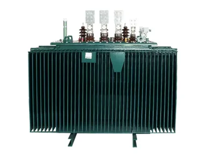
When it comes to distribution networks, you'll see a lot of dry-type and pad-mounted transformers. There's a good reason for that. They're safe, tough enough for different environments, and don't take up a ton of space. For instance, the iron core is made from high-quality, cold-rolled silicon steel sheets. It's built with a special three-stage joint structure that really helps the magnetic performance and cuts way down on losses. On top of that, the transformer comes with an intelligent temperature controller. This is a big deal for keeping it safe and reliable—and it has to be, especially since these things are always dealing with fluctuating loads.
![]()
Transformer drawings are indispensable for engineers conducting load analysis. They provide a visual representation of internal configurations and external dimensions, helping professionals predict performance under varying load conditions.
A well-documented distribution transformer drawing includes essential specifications such as rated capacity (KVA), voltage ratings (high and low), impedance percentages, no-load and load losses, connection methods (Yyn0 or Dyn11), tap changer settings, physical dimensions, and cooling mechanisms.
For example, Model: SCB10-315 Rated Capacity (KVA): 315 Rated Voltage (KV)-High Voltage: 11, 10.5, 10, 6.3, 6 Rated Voltage (KV)-Low Voltage: 0.4 Voltage Regulation Range: ±5% or ±2×2.5% Connection Method: Yyn0, Dyn11 No-load Loss (W): 880 Load Loss (W): 3470 No-load Current (%): 0.7 Short Circuit Impedance (%): 4. These values are crucial for simulating real-world load scenarios and determining transformer suitability for specific applications.
Transformer drawings also depict terminal arrangements and enclosure types—critical for installation planning and maintenance access. For instance, the casing can provide the further safety protection for the transformer, with the protection levels of IP20, IP23, IP30, IP33. Understanding these details ensures that installations comply with spatial constraints and safety regulations.
Transformer schematics offer insights that go beyond simple nameplate data. They are instrumental in system-wide planning activities such as load distribution strategies and fault coordination.
Drawings showing winding configurations allow engineers to assess phase loading accurately. With connection methods like Dyn11 or Yyn0 clearly marked on schematics—Connection Method: Yyn0, Dyn11—planners can ensure balanced phase currents across three-phase systems to minimize neutral current issues and improve efficiency.
Coordination between transformers and protection devices depends on impedance values and fault current calculations derived from schematics. For example,Short Circuit Impedance (%): 4 or Short Circuit Impedance (%): 6 directly affects relay settings and breaker selections within the protection scheme.
Voltage regulation is a key performance metric of any distribution transformer. Accurate interpretation of tap changer configurations within drawings allows precise voltage control under varying load conditions.
Many SHENGTE transformers offer a tap range of ±5% or ±2×2.5%, as stated in multiple models like Voltage Regulation Range: ±5% or ±2×2.5%. This flexibility enables fine-tuning during commissioning or operational changes without replacing hardware.
Secondary voltage ratings such as Rated Voltage (KV)-Low Voltage: 0.4 must align closely with downstream equipment requirements to avoid overvoltage or undervoltage conditions that could lead to inefficiencies or equipment damage.
SHENGTE’s distribution transformers exemplify engineering excellence through precision design and robust construction materials. Their dry type units feature a cross flow top blowing cooling fan enhancing the overload capacity of the transformer while maintaining low acoustic emissions—Noise Level (DB(A)): 43 to Noise Level (DB(A)): 49. These characteristics make them ideal for urban installations where space constraints and noise regulations are critical considerations.
Moreover,the low-voltage winding adopts a foil structure making the ampere turn more balanced, which minimizes hot spots under asymmetric loads—a common scenario in distribution networks.
Proper sizing ensures not only present reliability but also future scalability of power systems. Transformer drawings assist engineers in selecting units that meet both current demand profiles and anticipated growth trajectories.
Thermal performance is closely tied to losses documented within drawings—e.g., Load Loss (W): 2760 for SCB10-250 versus Load Loss (W): 15900 for SCB10-2000 models—allowing thermal modeling under peak conditions. The inclusion of axial cooling ducts further enhances heat dissipation capabilities as per the coil adopts axial cooling air duct, enhancing the heat dissipation capacity.
By analyzing rated capacities from drawings—ranging from Rated Capacity (KVA): 30 up to Rated Capacity (KVA): 2500—engineers can select appropriately sized units that accommodate projected load increases without necessitating early replacements or costly upgrades.
Modern grids require real-time monitoring capabilities integrated into core infrastructure components like transformers. Drawings indicating sensor placements or controller interfaces enable seamless integration with SCADA systems or IoT platforms.
The presence of features such as an intelligent temperature controller improves the operational safety and reliability, ensuring that temperature anomalies are detected early before they escalate into failures.
Q1: What information does a typical distribution transformer drawing include?
A typical drawing includes rated capacity, voltage levels on both sides, impedance percentage, winding configuration type (Dyn11/Yyn0), loss metrics (no-load/load), cooling method details, physical dimensions including weight/size layout plans, tap changer settings, terminal arrangements, casing type/protection level indicators like IP ratings.
Q2: Why is short circuit impedance important?
It determines how much fault current will flow during abnormal conditions; it also impacts voltage drop during normal operation which affects regulation quality across connected loads.
Q3: How do drawings help in maintenance planning?
They provide terminal layouts & component locations aiding technicians during inspection/replacement tasks; understanding enclosure types & ventilation paths helps avoid overheating risks during confined installations.
Q4: What makes SHENGTE transformers suitable for urban environments?
Their low-noise operation (Noise Level (DB(A)): 43–50), compact footprint (Size (MM): varies by model), smart temperature control systems & high-efficiency designs make them ideal where space & noise are constrained factors.