- All
- Product Name
- Product Keyword
- Product Model
- Product Summary
- Product Description
- Multi Field Search
Views: 0 Author: Site Editor Publish Time: 2025-03-22 Origin: Site
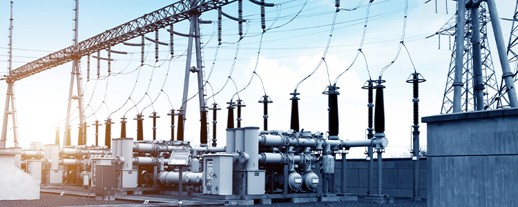
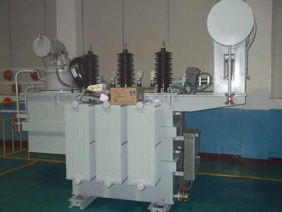
Substation auxiliary transformers are specialized power transformers dedicated to supplying electricity for staff and auxiliary equipment within a substation. Typically, dry-type transformers with ratings between 30 and 50 KVA are chosen, drawing power straight from the busbar. Their secondary winding(s) are generally configured for voltages such as 0.4 kV or 0.1 kV and are primarily used for lighting, control and protection circuits, and DC charging applications. This article explores the functions, categories, structural features, operating methods, and the main loads of these auxiliary transformers.
Reliable Power Supply
They ensure a consistent power source for both living facilities and production equipment within the substation, maintaining the smooth operation of on-site electrical systems.
They provide AC power for devices requiring operating voltage — such as protection panels, storage motors, SF6 circuit interrupter energy storage, and on-load tap changers — thereby supporting automation and safety monitoring systems.
They also deliver charging power to the substation's DC system, guaranteeing stable performance of critical monitoring, protection, and communication systems.
![]()
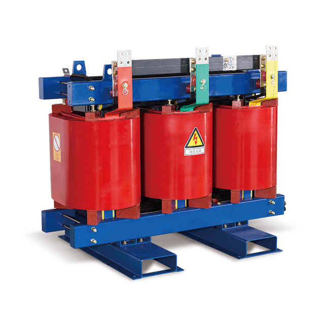
Depending on environmental conditions, capacity needs, and installation constraints, auxiliary transformers are mainly classified into two types:
1. Benefits: They feature a compact design and flexible mounting options, making them ideal for limited spaces such as basements, mid-level installations, or rooftops. Their design also enhances fire resistance and environmental performance.
2. Limitations: The cost per unit capacity is higher, so they are generally selected for lower capacity needs (around 30–50 KVA).
3. Selection Criteria: Preferred in areas where space is at a premium or where safety and environmental standards are stringent.

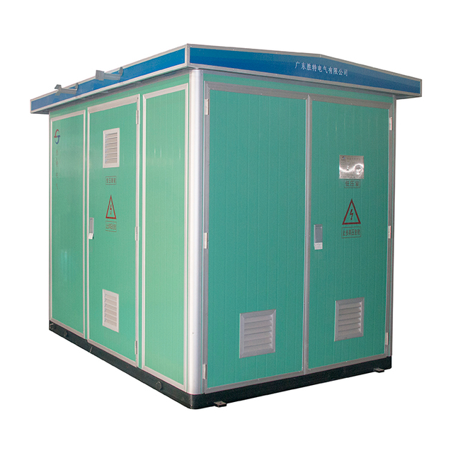
1. Benefits: They are available in larger capacities and are generally more cost-effective. They offer excellent heat dissipation.
2. Limitations: Their larger size requires stricter safety and fire protection measures, making them better suited for standalone substations or areas with ample space.
3. Selection Criteria: Chosen when high capacity is required or when sufficient installation space is available; also commonly used for temporary or outdoor applications.
For example, in distribution transformers integrated within switchgear, the internal transformer is usually a box type. Meanwhile, for temporary outdoor power, oil-immersed transformers are more common.
Taking the SCB10 series as an example, its notable technical characteristics include:
Superior Winding Design:
Copper or foil windings are reinforced with glass fiber and then encapsulated in epoxy resin via vacuum casting. This process provides high mechanical strength and excellent short-circuit and impact resistance.
High-Voltage Winding with Tap-Changer:
Pre-embedded copper inserts at both ends and in intermediate tap positions ensure accurate tap settings and robust mechanical rigidity, along with a neat appearance.
Advanced Core Design:
Constructed using high-grade grain-oriented cold-rolled silicon steel laminations and assembled using a 45° full-slope multi-step butt joint technique. A moisture-resistant, anti-rust resin insulation is applied to reduce noise and prevent overheating.
Robust Mechanical Fixing:
Elastic clamping devices maintain stable pressure on the windings, thus reducing operational noise.
Cooling System Integration:
The transformer is designed for natural air cooling with built-in vertical ventilation channels. Optionally, a forced air cooling system (e.g., a fan) can be added, increasing the output capacity by roughly 20%.
Comprehensive Temperature Protection:
A temperature controller monitors winding temperature via an embedded Pt100 resistor. It automatically regulates a cooling fan and provides fault alarms and over-temperature protection.
Within a transformer, the windings are arranged around the core to concentrate magnetic flux. Since the core's permeability is much higher than that of air, most magnetic flux remains confined within it, forming a closed magnetic circuit. When the current varies, so does the magnetic flux, inducing both electromotive force and eddy currents in the core.
Adverse Effects:
Energy loss, reducing overall efficiency.
Conversion of energy into heat, potentially causing local temperature rises that may impair safe operation.
Mitigation Measures:
Thin laminations, additional insulation layers, and efficient heat dissipation designs are commonly used to minimize these losses.
Common connection groups include Dyn11 and Yyn0, among others:
Dyn11 Connection:
Structure: The high-voltage side is delta-connected while the low-voltage side is wye-connected with a neutral tap.
Features: A phase shift of 30° exists between the sides, aiding in harmonic suppression and fault discrimination, while optimizing equipment capacity.
Yyn0 Connection:
Structure: Both sides are wye-connected with a neutral tap.
Features: No phase shift exists between sides, which is advantageous for four-wire power systems, but it does not provide a path for third harmonic currents.
Additional configurations, such as delta or zigzag connections, offer alternative solutions. Zigzag connections, for instance, combine certain benefits but may require roughly 15.5% more turns, thus increasing cost.
Standards such as DL/T 5155-2002 and GB 50059-1992 provide guidelines for station auxiliary transformers. Key requirements include:
Redundancy:
Typically, two auxiliary transformers of equal capacity are used, allowing mutual backup. If only one main transformer is present, the other unit should be sourced externally to ensure uninterrupted power.
Backup Configuration:
For substations operating at 30kV–500kV, it is recommended that at least two auxiliary transformers be installed, with an additional unit provided by an external source if possible.
Load Management:
Station loads are categorized into Class I, II, and III based on their impact on production and safety, guiding the design of power supply and backup systems.
Classification of Loads:
Class I: Critical loads (e.g., transformer cooling, communication, protection systems) that require very high continuity.
Class II: Loads that can tolerate short interruptions but need rapid recovery to avoid production loss.
Class III: Loads with minimal impact on production, where longer outages are acceptable.
In summary, substation auxiliary transformers are vital for ensuring reliable power in substations. By employing advanced winding designs, robust cooling systems, proper connection groups, and redundant configurations, the overall reliability and safety of substation power supply can be greatly enhanced.