- All
- Product Name
- Product Keyword
- Product Model
- Product Summary
- Product Description
- Multi Field Search


Views: 0 Author: Site Editor Publish Time: 2024-09-28 Origin: Site
In recent years, the rapid growth of installed capacity in both offshore and onshore wind power has driven a series of surging demands for wind power transformers. However, the fierce competition within the wind power industry has also brought significant cost pressures, which are constantly passed down from highly competitive turbine manufacturers to downstream suppliers. As a result, wind power transformer suppliers often find themselves in the difficult position of "losing money just to stay in the game." Under immense cost pressure, manufacturers have spared no effort in reducing costs, cutting expenses again and again.
This article presents a case study of the failure of a 3500kVA oil-immersed wind power transformer. While this case cannot directly demonstrate the harm that cost reduction can cause to product reliability and safety, it at least highlights that “bold innovations” carried out without thorough analysis and rigorous validation can lead to "paying the price." Let’s take a closer look at the lesson learned from this incident.
The transformer’s fault was relatively minor, which in turn left us with a clear original "crime scene" that, upon inspection, allowed us to deduce the cause of the accident through a simple analysis. As shown in the image below, this is an oil-immersed transformer with an elongated oval winding and a copper foil-wound low-voltage coil. The fault occurred in the area where the long oval winding transitions into the circular portion of the coil.


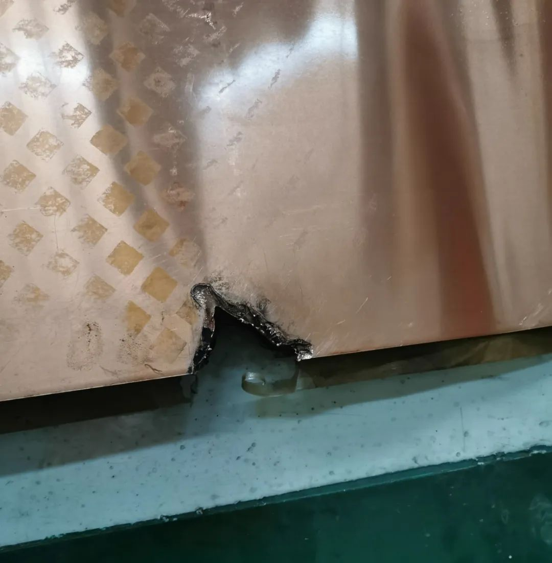
The copper foil of the winding is relatively thick, measuring 2.5mm, and the interlayer insulation consists of two layers of 0.07mm thick adhesive paper. As shown in the image below, it can be more clearly seen that an inter-turn short circuit occurred at the point where the two layers of copper foil intersect between the straight line and the circular section.


The image below provides a clearer view of the appearance of the inter-turn short circuit. Additionally, the break point visually shows just how thick the copper foil truly is.


This product underwent rigorous routine and type tests at the factory, including lightning, induction, and power frequency withstand voltage tests, all of which showed no abnormalities. Additionally, a temperature rise test was conducted on the first unit. According to the data from the site investigation, no significant system abnormalities were observed during the product's operation—there were no impact loads, system overvoltage, or abnormal switching operations. So, how did two transformers, both operating normally, fail within roughly two consecutive weeks, with such similar fault modes?
From the brief introduction above, it's likely that you've already guessed the cause: it is directly related to the structure of this product.
Electromagnetic Force Analysis of the Elongated Oval Coil


To emphasize the analysis of each layer of copper foil in the foil-wound coil within the leakage magnetic field, we specifically performed layered modeling on the low-voltage winding. This means that both the copper foil and the adjacent interlayer insulation were modeled. Additionally, to ensure computational accuracy, we set finer mesh division sizes for the copper foil and interlayer insulation sections.


First, we solved the two-dimensional spatial distribution of the leakage magnetic field, and the results are shown in the figure above. To further study the magnitude and direction of the leakage magnetic field in various parts, we performed a three-dimensional mesh division on the model and conducted a 3D leakage magnetic field calculation. The results are shown in the figure below. On this basis, we calculated the force conditions on the winding and each layer of copper foil, as shown in the figure below. From the results, it can be seen that the low-voltage winding is subjected to an inward force under load conditions. Moreover, the force distribution is uneven: the upper and lower ends experience higher and more concentrated force intensity, while the middle part experiences smaller and more uniform forces.


Analysis and Inference of the Failure Causes
1. Copper Foil Too Thick: The copper foil is excessively thick, and the edge rounding treatment is insufficient. During on-site inspections, the sharp edges of the copper foil even pose a risk of cutting the skin.
2. Interlayer Insulation Too Thin: The adhesive paper used for interlayer insulation feels extremely flimsy and fragile. In contrast, the composite insulation paper used in dry-type transformers offers much more reliable flexibility.
3. Overemphasis on Cost Reduction: The third point, which is also the main focus of this article regarding cost reduction, is that elongated oval coils are becoming increasingly common in copper-wound transformers. In the pursuit of the ultimate copper-to-iron ratio, manufacturers are stretching the oval ratio more and more. This increases the difficulty of the manufacturing process, leads to unexpected issues during winding, and introduces various risks of increased electromagnetic forces during normal operation.
4. Attribution of Failure Cause: For the ultimate cause of the failure in this case, I would attribute it to an extreme cost-reduction scheme and structural design that, combined with defects in raw materials, allowed potential risks to develop into an actual short-circuit failure. Fortunately, the protection system was sufficiently sensitive, preventing serious accidents like fires or explosions.