- All
- Product Name
- Product Keyword
- Product Model
- Product Summary
- Product Description
- Multi Field Search
Views: 0 Author: Site Editor Publish Time: 2025-12-11 Origin: Site
What Are the Key Principles Behind Connecting a 3 Phase Current Transformer?
How Should You Choose Between a Delta or Wye Connection for CTs?
How Do You Ensure Safe and Reliable Installation of 3 Phase CTs?
How Can You Match CT Performance with Distribution Transformers?
How Does SHENGTE Support High Precision Power Monitoring Applications?

![]()
This guide covers the main rules for properly linking a 3 phase current transformer in electrical networks. Correct setup demands keeping the right phase order and same polarity marks across all units. This practice guarantees true readings for meters and safe action from protection devices. Picking the proper ratio and watching the load on the secondary side help stop overload and wrong values. Choosing between star or triangle wiring depends on the job, such as guarding transformers or finding earth faults. Safe work includes firm mounting, shielded cables, and always grounding the secondary loop. Matching the CTs with suitable power transformers, especially SHENGTE models, brings steady and exact results in daily use.
Correct phase order and uniform polarity stand as basic needs when setting up a 3 phase current transformer system. Wrong order can create false power readings and confuse energy meters. The system may mix up active and reactive power flow.
Polarity mistakes often cause trouble as well. One reversed CT can show negative numbers or send protection relays in the wrong direction. Phase angle errors appear quickly. Therefore, every CT must face the same way. The arrow or marking P1 to P2 has to follow real current direction. Secondary terminals S1 and S2 need the same wiring pattern across the whole set.
Uniform polarity keeps the vector addition correct. Any difference brings big mistakes, mainly in differential schemes or when several CTs feed one relay.
Choosing the right ratio prevents the core from filling up too much or giving weak signals. The ratio should match the normal current of the line or equipment or too small a ratio leads to saturation even under regular load. Fault currents then push the core far beyond limits, and the output becomes distorted.
The burden, meaning everything connected to the secondary side, also plays a big role. Cables, meters, and relays all add resistance and reactance. This total must stay inside the maker’s limits. Too heavy a burden changes the waveform and harms relay timing.
For example, dry-type units like the SCB10-800 show low no-load current of just 0.5 percent. Accurate CT sizing keeps protection settings reliable across light and heavy loads.
Triangle and star connections serve separate tasks in a 3 phase current transformer setup. Triangle wiring suits differential protection best. It naturally removes zero-sequence parts, so only phase-to-phase faults appear clearly, which helps find internal problems inside motors or transformer windings.
Star wiring, however, works better for earth fault detection and normal metering. Each phase has its own path to a common neutral point. Unbalanced loads or ground currents become easy to spot.
The choice depends on what the network needs most. Systems that require neutral current measurement benefit from star-connected CTs.
Open delta uses just two CTs instead of three, saving money and space in balanced networks. The third phase value comes from simple math inside the relay.
Older plants often use this style when ground current monitoring is not required. Yet full fault coverage suffers because one phase stays unseen. Serious networks, especially those with strong oil-immersed transformers, gain better safety from complete three-CT wiring in either star or triangle form.
Firm fixing on busbars or cables stops movement when heavy fault currents flow. Strong magnetic forces appear during short circuits and any shift can break the unit or change accuracy.
Use shielded cables for secondary wiring to reduce electromagnetic interference, particularly in industrial environments with high transient noise levels. Shielded wiring ensures signal integrity between CTs and connected relays or meters.
Never leave secondary terminals open while primary current flows. High voltage builds up fast and can destroy insulation or harm workers. Shorting bars or automatic links must stay in place until the circuit is fully safe.
Grounding one point on the secondary side removes floating voltages. Capacitive effects or insulation faults can create dangerous levels otherwise. A solid earth link also helps relays see ground faults clearly.
Modern dry-type transformers often include smart temperature controls. Proper grounding supports those systems by keeping transient spikes away from sensitive electronics.
Several values must line up for smooth operation. Voltage rating comes first. A 10 kV CT belongs with 10 kV transformers. Current rating follows the transformer’s full-load value. An 80 kVA unit at 400 V draws about 115 A per phase, so CTs near that mark give the best results.
Heat behavior matters too. Models like the S11-M-30 use strong insulation that handles high temperatures. Pairing them with CTs built for warm locations avoids problems during summer peaks.
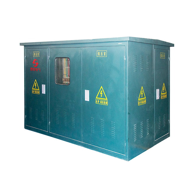
The S11 80kVA 10kV 400V High Performance 3-Phase Oil Filled Type Distribution Transformer works smoothly with accurate CTs. Its low-loss core cuts wasted energy and good cooling keeps performance steady hour after hour.
![]()

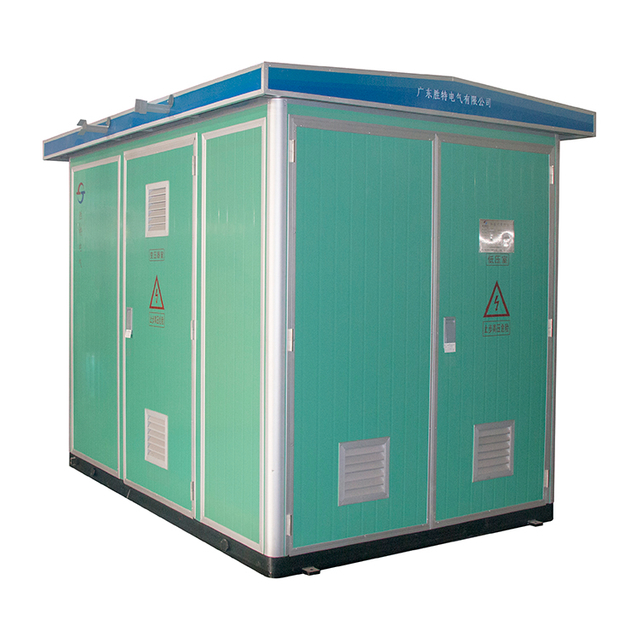
For larger loads, SHENGTE supplies the S11 100kVA 10kV 400V 50Hz Frequency 3Phase Oil Cooled Type Distribution Transformer. This unit handles heavy duty cycles while staying compatible with high-ratio CTs.
![]()

SHENGTE builds transformers that last long and waste little power. Strong cores, careful winding, and strict tests meet global standards. Engineers choose SHENGTE when networks face changing loads day after day.
Smart grids and modern substations need dependable partners. SHENGTE products connect easily with advanced meters and fast relays. The S11 100kVA 10kV 400V 50Hz Frequency 3Phase Oil Cooled Type Distribution Transformer proves this match in real installations.
Q: Can I connect three single-phase CTs instead of using a dedicated three-phase unit?
A:Yes. Three separate single-phase units work well if every one shares the same ratio, polarity marks, and mounting care. Consistency across all three keeps readings true.
Q: What happens if I leave a current transformer’s secondary open while energized?
A: Dangerous high voltage appears instantly. Insulation can break, and people nearby face serious risk. Always short the secondary before any work begins.
Q: How do I verify that my CT installation is correctly phased?
A: A phase rotation tester or relay vector display helps during startup. Compare measured angles with expected diagrams to confirm proper order.