- All
- Product Name
- Product Keyword
- Product Model
- Product Summary
- Product Description
- Multi Field Search
Views: 0 Author: Site Editor Publish Time: 2026-10-29 Origin: Site
For a battery energy storage system, the power and energy ratings of the system need to be distinguished from the transformer loading, which is determined by the operating envelope of the PCS. The battery MWh describes the amount of energy that can be stored for a certain amount of time. The transformer kVA or MVA, however, depends on PCS output, power factor, voltage, operating cycle and other site-specific factors. Start with the single-line diagram of the BESS and the associated operating limits.
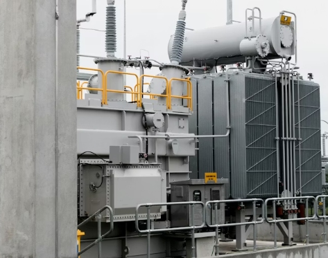
The distribution transformer of a grid-connected system is typically installed between the medium-voltage network and the AC-side of the power conversion system. Switchgear, protection and metering are usually connected to the transformer in order to define the connection to and the switching off of the transformer. The PCS converts AC power to DC power for charging and vice versa for discharging. As a result, the distribution transformer performs voltage transformation, isolation and current transfer in a system for charging and discharging alike for import and export.
A BESS can charge and discharge at different maximum power levels. In addition to that, it can also provide reactive power or perform other grid services as long as the active power is below the maximum. For that reason, a smart grid energy storage transformer needs to be designed based on the complete PCS capability curve. Maximum charging and discharging MVA, reactive power, and the respective time share need to be compared. The highest MW does not necessarily mean the highest current.
Data required for PCS interconnection study: PCS AC voltage, PCS rated MW, PCS maximum MVA, PCS power factor, PCS frequency, PCS overload duration, PCS operating schedule. Interconnection study defines: source voltage limits, fault level, grounding, protection. Distribution transformer selection data: ambient temperature, altitude, contamination, corrosion exposure, layout.
Apparent power is typically expressed as the transformer capacity in MVA. Using the known active power in MW, the apparent power in MVA can be calculated by dividing by the power factor. Thus 1.8MW at a 0.90 power factor equals 2.0MVA before any project-specific derating is applied. This must also be calculated for charging, discharging and for the reactive power. Then check the line current for the selected voltage against the ratings for the transformer, cables, busbar and switchgear.
A distribution transformer has to connect the grid voltage to the PCS AC voltage. The specification of a suitable distribution transformer has to include rated primary and secondary voltage and frequency, as well as the tap range, the vector group, the neutral treatment and the grounding method of the secondary. A tap changer approves a source-voltage range for a given transformer ratio. However, a tap changer is not able to correct an unsuitable transformer ratio. The vector group and the grounding of a distribution transformer have an influence on the zero-sequence current as well as on the dimensioning of the protection and the interaction with the PCS.
Even though an oil-type transformer is running 24/7 for continuous load, it has to be checked for BESS cycling as well. The temperature of the winding and oil changes differently for low load, for charging and for discharging. Thus, even short overloads have to be checked for duration, starting temperature and cooling possibility. For thermal check of transformer daily load profile, seasonal ambient temperature and percentage of time run at low load have to be checked.

No-load loss occurs whenever the transformer is energized, even if the BESS is idle. Load loss rises with current and changes with conductor temperature. An energy-saving distribution transformer should therefore be compared using the expected annual operating profile rather than a single efficiency value. A project with long standby periods may place greater weight on no-load loss, while a frequently cycled installation may place greater weight on load loss and thermal performance.
Nonsinusoidal current can be drawn or delivered by PCS equipment. The harmonic currents can increase the winding eddy-current loss, the structural stray loss and hot-spot temperature. Instead of using a purely sinusoidal load, the study should use the expected current spectrum and the respective operating duty. If the additional material heating is significant, the design may require derating, or even a different winding layout, additional thermal margin, or even a custom-made transformer for the respective measured current spectrum.
Short-circuit impedance has an influence on possible short-circuit current, on voltage drop and on current sharing at paralleled units. Short-circuit current caused by magnetizing inrush must not trigger relays and must be avoided in order to enable a smooth start-up of generators. Protection coordination consists of transformer differential/overcurrent protection and grounding, as well as surge protection, switchgear breakers and PCS fault behavior. The distribution transformer must be selected in coherence with the rest of the BESS electrical system.
Both oil-immersed and dry-type designs can be suitable. However, the site has the final say and indoor rooms, outdoor yards, fire separation, ventilation, environmental issues and maintenance are all factors that need to be considered when selecting a preferred design. Liquid-filled equipment requires containment and separation to various degrees, while dry-type requires controlled ventilation, enclosure and clean air to prevent contamination. The preferred design must adhere to local codes and the risk criteria of the owner.
For a three-phase oil-immersed distribution transformer for an outdoor BESS installation, the ambient temperature, altitude, solar radiation, rain run-off, flood level, corrosion and working clearances need to be checked. The civil design must check the load on the foundation, allow for lifting, cable entry, oil containment, earthing, lightning protection, fencing and access for future inspection. The final dimensions and accessories can then be agreed.
The purchase specification should list guaranteed no-load and load losses as well as guaranteed impedance values and guaranteed temperature-rise limits. The insulation level, the tap arrangement, the vector group, as well as the cooling type must also be specified. The purchase specification should also list the routine tests as well as the project-specific tests, the required drawings, the terminal details and the monitoring accessories. Furthermore, the document language as well as the interface schedules must be clearly defined in order to avoid the unexpected discovery of incompatible cables, switchgear or control equipment after manufacture.
The SHENGTE S11-M-2000/10 model is supplied as an oil-immersed type. The S11-M-2000 schedule details the high-voltage options of 6kV, 6.3kV, 10kV, 10.5kV and 11kV plus the 0.4kV secondary, plus connection options of Yyn0 or Dyn11 and tap change range of ±5% or ±2 × 2.5%. Weights are 1,050kg of oil and 2,600kg of body, plus a track gauge of 920mm x 920mm. It is recommended that the selected voltage and connection are compared with the PCS and grounding design prior to ordering.

This data for the S11-M-2000 is 1,940 W no-load loss and 18,300 W load loss and 0.4% no-load current and 5% short-circuit impedance. Our S11-M storage tanks are made of cold-rolled steel which has been degreased, cleaned of rust and phosphated before being protected by protective paint against rain, moisture and salt spray. The rubber sealing rings form a tight seal between the oil and outside air. The loss data must be related to the planned charge, discharge and standby profile for an energy-saving distribution transformer.
The S11-M-2000/10 is listed with outside dimensions of 2,030mm x 1,340mm x 2,000mm and a total weight of 4,500kg. S11-M oil-immersed transformers utilize cylindrical high- and low-voltage windings. The coils and core are vacuum-dried and the oil is vacuum-filtered prior to filling. Corrugated tank plates allow for oil-volume changes due to temperature. A helical winding has longitudinal oil ducts, and the support structure is designed for short-circuit forces. The laminated core is made of silicon-steel sheets with thicknesses under 0.35mm. The factory is over 12,000 m² in size and is equipped with all necessary machining and testing equipment. Design, production, testing, assembly, installation and commissioning are all conducted in-house. Required for definition of a specific BESS configuration are the datasheet for the PCS, charge and discharge limits, power-factor range, voltages, harmonic spectrum, fault level, protection philosophy, site details, layout, accessories required and test requirements.
Choose a BESS transformer from within the AC operating envelope of the transformer. Calculate maximum credible MVA. Ensure grid and PCS voltages are matched. Check for cyclic thermal duty. Compare losses to the operating profile. Harmonics, impedance and protection all need to be coordinated. We at SHENGTE can then review whether the S11-M-2000/10 distribution transformer is suitable for your project or if you require a different rating.