- All
- Product Name
- Product Keyword
- Product Model
- Product Summary
- Product Description
- Multi Field Search
Views: 0 Author: Site Editor Publish Time: 2026-09-10 Origin: Site
1.How a Distribution Transformer Works
2.Distribution transformer kVA and load calculation
3.Match voltage, phase, and electrical parameters
4.Distribution transformer uses and installation conditions
5.SHENGTE S11-M-630/10 transformer
Selecting a distribution transformer is a calculation exercise, not a guess based on the largest motor or the total of every nameplate. Engineers need a realistic load schedule, the required kVA, compatible primary and secondary voltages, the correct phase connection, and enough capacity for credible growth. This guide follows that sequence so a buyer can move from a project load list to a technically reviewable specification. The aim is a dependable distribution transformer that operates within the electrical system.
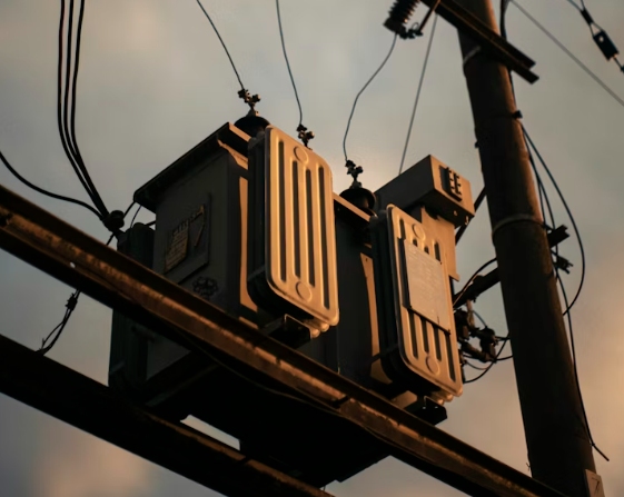
The basic working principle here relies on electromagnetic induction. An alternating current flows through the primary winding. This flow creates a shifting magnetic flux inside the laminated steel core. Next, this flux connects with the secondary winding. As a result, it induces a distinct voltage. The specific turns ratio sets up the exact voltage relationship between the primary and secondary sides. Meanwhile, the system frequency stays exactly the same. The secondary winding then supplies energy to a connected load. During this process, power moves across the magnetic field. Therefore, no direct electrical link exists between the two separate windings.
First, the primary winding takes in the main utility or feeder voltage. Second, the central core supports the active alternating magnetic field. Finally, the secondary winding sends out a reduced or matching voltage for downstream equipment. Overall equipment design relies heavily on proper insulation and effective heat removal. It also requires careful planning of the winding arrangement, system impedance, and specific load duty.
The core provides a low-reluctance magnetic path. High- and low-voltage windings create the turns ratio and withstand electrical, thermal, and mechanical stresses. Solid insulation separates conductors from the core and tank. In an oil-immersed design, transformer oil provides insulation and heat transfer. The tank contains the active parts, bushings connect external cables, and corrugated surfaces accommodate oil expansion while aiding heat dissipation.
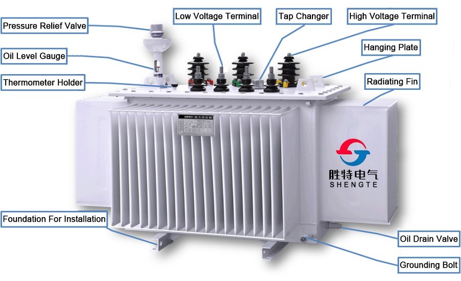
A physical drawing shows the tank, bushings, corrugations, lifting points, and clearances. A circuit or single-line diagram shows incoming voltage, winding connection, neutral, grounding, protection, and outgoing feeders. Use the physical drawing for foundation and maintenance space, and the electrical drawing for voltage ratio, vector group, fault path, and protection interfaces.
Start with connected load, but do not treat every load as operating at full output at the same time. Separate continuous from intermittent loads, record motor starting duty, and identify rectifiers, variable-speed drives, UPS equipment, and other nonlinear loads that may add harmonics. Apply demand or diversity factors only when the operating pattern supports them.
Transformer capacity is expressed in apparent power because windings carry current created by real and reactive power. For known real power, use:
Required kVA = real kW ÷ power factor
For example, 420 kW at a 0.90 power factor requires about 467 kVA before adding any project-specific allowance. For a balanced three-phase system, apparent power can also be checked with:
S = √3 × line voltage × line current
Compare the result with the operating profile, not just a theoretical peak. A low power factor can force a larger rating even when measured kW appears acceptable. Capacitor correction may reduce reactive demand, but harmonics and switching behavior still require review.
After calculating kVA, check current against cable, breaker, and bus ratings. Motors may draw several times running current during acceleration, while impedance affects voltage dip and fault current. Nonlinear loads can increase heating even when average kVA looks moderate. Ambient temperature, altitude, ventilation, and duty cycle may require derating. Add growth allowance tied to a documented forecast; an arbitrary margin can oversize the unit and increase no-load losses. The final rating should cover credible peak duty without hiding poor load data.
Confirm utility or generator voltage, the operating range, and downstream voltage. A tap range can accommodate defined source variation, but taps do not replace a correct ratio. Check frequency, insulation level, neutral availability, and the switchgear interface. A distribution transformer with the right kVA but wrong secondary voltage can cause nuisance trips, overheating, or poor motor performance.
Decide whether the project needs single-phase or three-phase service, then document neutral and grounding requirements. Balance three-phase loads where practical, and size the neutral for expected unbalance and harmonics. Confirm the vector group against protection settings and downstream equipment.
Short-circuit impedance influences fault current and voltage drop. Lower impedance can support voltage regulation but may increase fault duty; higher impedance can limit fault current while causing more voltage drop under heavy load. Coordinate the value with feeder conductors, breakers, fuses, grounding, and relay settings. Review no-load and load losses separately for lifecycle cost, and confirm that protection, cable, and installation studies agree.

Common applications include commercial buildings, industrial processes, infrastructure, renewable-energy collection, and utility feeders. Each transformer application has a different load curve, duty cycle, voltage tolerance, and continuity target. These differences influence kVA selection, impedance, cooling, metering, and protection.
This three-phase oil-immersed unit can be appropriate when the network, site, and safety requirements support liquid insulation and outdoor or utility-style installation. Oil transfers heat from the windings and core to the tank, while sealed construction isolates the oil from surrounding air. SHENGTE oil-immersed designs use stacked silicon-steel cores, cylindrical windings, filtered oil filling, and corrugated tanks. Final choice depends on fire rules, environmental conditions, access, and the owner's maintenance strategy.
An outdoor unit requires more than a weatherproof enclosure. Check ambient temperature, altitude, solar exposure, contamination, drainage, flood level, foundation loading, cable bending space, lifting access, and safe clearances. Confirm earthing, lightning protection, fencing, oil containment, and inspection routes with the civil and electrical teams. These checks can change the rating, accessories, layout, or preferred construction.
The SHENGTE S11-M-630/10 applies the checklist. The model is rated at 630 kVA, with high-voltage options of 11, 10.5, 10, 6.3, or 6 kV and a 0.4 kV low-voltage rating. The listed regulation range is ±5%, with Yyn0 and Dyn11 connection methods. These values support comparison with a project single-line diagram, but do not make the model universally suitable.
The loss and physical data are also important. S11-M-630 has 810 W no-load loss, 6200 W load loss, 0.6% no-load current, and 4.5% short-circuit impedance. Oil weight is 330 kg and total weight is 1830 kg. Overall dimensions are 1540 × 1010 × 1510 mm, with a 660 × 660 mm track gauge. Our team uses these values to review transport, foundation, clearances, fault calculations, and lifecycle comparisons, not to make unsupported efficiency promises.
At SHENGTE, we ask for the load schedule, maximum demand, power factor, source and load voltage, phase arrangement, vector group, fault level, site conditions, and growth plan before recommending a configuration. Our products are selected around project data, not a capacity label alone. If demand, voltage, outdoor conditions, and protection study align, S11-M-630/10 can be evaluated as the candidate transformer; otherwise, we review a different rating or configuration.
Correct sizing follows a clear chain: define realistic maximum demand, convert kW to kVA, verify three-phase current and growth, match primary and secondary voltage, confirm phase and vector group, review impedance and protection, and check the installation site. The distribution transformer should fit the complete power system, including cables, switchgear, grounding, maintenance access, and future expansion. SHENGTE can review the S11-M-630/10 or another configuration when the project data is complete, helping the buyer make a technically defensible selection.