- All
- Product Name
- Product Keyword
- Product Model
- Product Summary
- Product Description
- Multi Field Search
Views: 0 Author: Site Editor Publish Time: 2026-02-11 Origin: Site
![]()
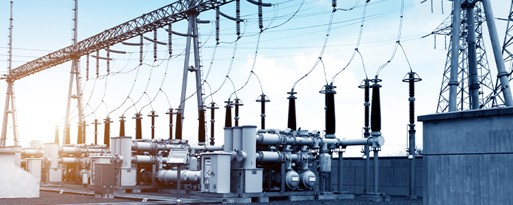
The reliable functioning of any electrical distribution system depends heavily upon the physical condition and electrical soundness of its central components—the transformers. Although detailed design standards and thorough factory assessments establish a solid foundation for expected capability, moving equipment from a protected production setting into real-world placement introduces numerous factors capable of either safeguarding or gradually undermining the device’s service duration. For teams responsible for vital power infrastructure projects, the on-site assembly stage represents a highly exacting procedure in which proper positional alignment, surrounding thermal conditions, and thorough readiness checks largely determine both long-term ownership expenses and overall network dependability.
The surrounding location chosen for transformer placement effectively becomes its essential external cooling arrangement and protective system. Transformers produce considerable amounts of heat resulting from magnetic core losses together with conductor resistance losses, so prevailing atmospheric circumstances combined with the physical positioning of the unit are equally significant as the built-in cooling arrangement itself. Insufficient attention paid toward appropriate site characteristics frequently accelerates deterioration processes in insulating materials, thereby potentially reducing by half the anticipated operational lifespan of otherwise durable assets.
Adequate removal of generated heat stands as the single most crucial necessity for successful placement. Units depending upon either natural convection air movement or mechanically assisted airflow demand sufficient exchange volumes calculated according to peak load-related dissipation figures. Clear pathways for incoming fresh air and outgoing warmed exhaust must remain unobstructed in the containing structure or surrounding space to avoid repeated recirculation of already heated air across sensitive coil surfaces, which may cause winding temperatures to exceed established thermal endurance thresholds of the chosen insulating substances.
Although contemporary energy-efficient models incorporate strengthened tolerance margins against such conditions, proper external surroundings remain indispensable for effective expulsion of accumulated thermal energy. Advanced designs frequently incorporate directional top-mounted fans arranged to produce transverse airflow patterns, thereby substantially increasing overload handling potential, but these auxiliary mechanisms deliver meaningful benefits exclusively when constant supplies of fresh, uncontaminated external air remain accessible.
Safeguarding interior assemblies against water vapor penetration, airborne salt particles, and chemically aggressive dust represents an absolute requirement for sustained operational trustworthiness. In enclosed premises or locations demanding heightened fire safety considerations, the inherent protective qualities offered by the selected insulation medium constitute the foremost barrier against external threats. Choosing equipment featuring elevated dielectric withstand capability alongside strong resistance toward ambient degradation permits strategic positioning directly adjacent to major consumption points, thereby decreasing associated conductor losses while simultaneously simplifying overall facility layout requirements.
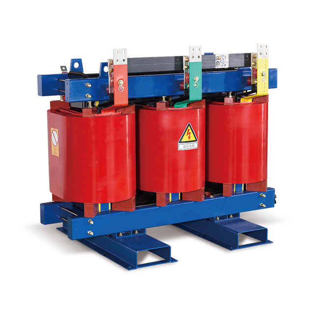
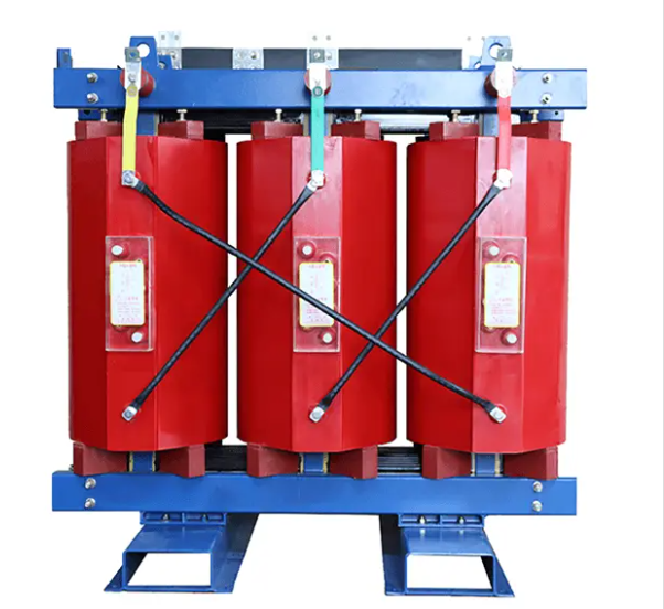
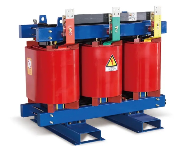
For example, the SCB10 630kVA 6kV 400V Customized Three-Phase Resin Casting Dry-Type Power Transformer specifically addresses many of these environmental challenges through purposeful engineering. High-voltage coil sections undergo complete vacuum encapsulation using high-grade epoxy resin, establishing a robust, impermeable solid covering capable of reliable service even under conditions approaching complete atmospheric saturation. Elimination of fluid containment hazards combined with inherently low partial discharge characteristics enables confident deployment in restricted metropolitan districts or demanding industrial premises without sacrificing either personnel protection standards or electrical efficiency expectations.
![]()
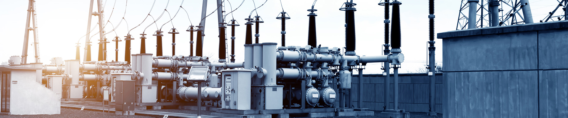
Correct positional setup, along with secure interconnection of transformers, extends considerably beyond routine material handling procedures and tends to demand thorough awareness regarding various mechanical influences capable of affecting electromagnetic behavior characteristics. Even minor departures from prescribed mounting geometry may generate persistent, though initially subtle, detrimental stresses.
Provision of an adequately stable and precisely horizontal supporting surface constitutes an essential precondition for achieving acceptably quiet and highly efficient transformer operation. Uneven base conditions subject the laminated core, typically fabricated from carefully processed cold-rolled oriented silicon steel, to unintended mechanical loading. Resultant distortions modify intended magnetic flux pathways, thereby intensifying magnetostrictive expansion/contraction phenomena and producing correspondingly elevated acoustic emissions. Of greater operational significance, imperfect levelness imposes additional loading upon clamping assemblies and anchoring elements, potentially compromising structural integrity when severe electromagnetic forces develop during network fault occurrences. The use of accurate optical or laser-based leveling instruments during positioning procedures ensures continued vertical alignment of core limb sections, consequently preserving symmetry in the complete magnetic circuit configuration.
The successful execution of sophisticated electrical infrastructure initiatives depends substantially upon the selection of an appropriately qualified equipment supplier whose offerings demonstrate consistent long-term dependability. SHENGTE maintains more than fifteen years of focused experience bridging advanced ecological distribution requirements with uncompromising manufacturing accuracy. Operating from an extensive 12,000-square-meter purpose-built facility situated in Guangdong province, our company functions as an integrated center encompassing product conception, rigorous validation procedures, and complete assembly operations, all conducted under unified management in strict conformity with ISO9001 quality management principles together with applicable IEC technical specifications. Recognition as an approved provider serving major national transmission entities, including State Grid Corporation alongside China Southern Power Grid, underscores a commitment toward the development of exceptionally trustworthy equipment serving as dependable core elements in contemporary electrical networks.
Combining forward-looking research activities with dedicated post-delivery support infrastructure ensures delivery of enduring strategic value extending well beyond conventional hardware supply arrangements.
Overall electrical continuity remains fundamentally limited by the quality maintained at individual termination interfaces. Elevated contact resistance developing at either primary-side or secondary-side connection points frequently constitutes the principal origin of concentrated thermal accumulation. Installation protocols, therefore, mandate precise adherence to manufacturer-specified torque values applied uniformly across all bolted joints and pressure connections. Application of excessive force risks thread deformation or lug distortion, while insufficient tightening permits microscopic separation gaps conducive to progressive surface oxidation and eventual discharge activity.
Strategic utilization of compatible conductive pastes or anti-oxidant compounds at mating surfaces effectively restricts atmospheric oxygen and moisture access, thereby sustaining intended conductivity performance across foil-type low-voltage configurations or conventional wire-wound high-voltage assemblies throughout extended service periods.
The critical transition phase linking completed physical installation with actual service energization necessitates implementation of comprehensive verification procedures. Despite arrival accompanied by detailed manufacturer-issued compliance documentation, transportation-induced stresses together with site-specific handling conditions can introduce previously undetected anomalies requiring identification before initial voltage application.
Conducting on-site insulation resistance measurements using properly calibrated high-voltage test instrumentation provides the most conclusive evidence confirming the absence of transit-related or installation-induced degradation. Comparative evaluation of obtained readings against original factory reference values enables detection of possible moisture ingress or physical compromise in dielectric barriers. Substantial deviation from benchmark figures signals the necessity for remedial investigation before commissioning, thereby establishing fundamental protection against potentially devastating in-service dielectric breakdown events. For units employing resin-encapsulated construction, supplementary confirmation that partial discharge activity remains confined in specified acceptance thresholds further verifies preservation of vacuum-impregnation integrity despite mechanical handling exposures.
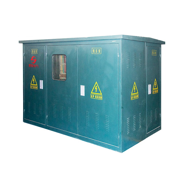
Contemporary distribution practices in densely developed urban territories increasingly favor consolidated, space-efficient installations incorporating both power transformation and associated protective switching apparatus in unified protective enclosures. Such integrated arrangements streamline placement activities while simultaneously demanding meticulous validation of internal interconnection continuity alongside unobstructed cooling airflow routes. Representative examples include the ZGS11 1600kVA 10kV 0.4kV Dyn11 Connection Box Type Pad-Mounted Substation Transformer, which combines core assembly, high-voltage sectionalizing switches, and protective fusing elements inside a completely sealed, dielectric-fluid-containing enclosure. This compact “American-style” approach delivers exceptional service reliability, enhanced physical security features, and superior weather resistance while requiring significantly reduced footprint compared to conventional substation configurations. During placement of such assemblies, primary attention centers upon the correct coupling of incoming/outgoing cable terminations together with the proper execution of system grounding connections, given that internal coordination between major functional elements has already undergone optimized factory integration.
![]()

Systematic enhancement of transformer capability constitutes an ongoing sequence commencing with exacting design development and concluding with scrupulous on-site implementation practices. Emphasis placed upon sustained thermal equilibrium, accurate mechanical positioning, and exhaustive readiness verification collectively ensures distribution networks achieve superior levels of operational security combined with efficient energy delivery, thereby satisfying rigorous expectations characteristic of present-day electrical supply environments.
Q: If a transformer produces excessive noise immediately after installation, what are the most likely causes?
A: Audible emissions from transformers primarily originate from cyclic dimensional changes occurring in ferromagnetic core materials subjected to alternating flux. Imperfect foundation flatness introduces uneven loading capable of markedly intensifying these magnetostrictive vibrations. Additional frequent contributors encompass insufficiently secured external clamping hardware oscillating synchronously with supply frequency alongside acoustic amplification resulting from nearby reflective surfaces or resonant structural elements functioning as unintentional sound radiators.
Q: How does forced air cooling (AF) affect the installation requirements of a dry-type transformer?
A: Incorporation of mechanically driven airflow augmentation enables dry-type transformers to sustain substantially elevated continuous loading—frequently reaching approximately 120% of nominal nameplate rating under controlled conditions. Implementation of such enhancement necessitates the provision of dependable auxiliary power circuits dedicated to cooling fan operation alongside properly interfaced thermal monitoring instrumentation integrated in facility supervisory systems. Regarding placement considerations, precise positioning of critical temperature detection elements becomes essential to ensure timely activation of forced ventilation prior to insulation materials approaching established maximum allowable temperatures.
Q: What are the main benefits of installing a pad-mounted "American-style" substation compared to a traditional open-style transformer?
A: Foremost advantages center upon greatly reduced spatial requirements combined with markedly improved safety characteristics. Units belonging to the ZGS11 series fully enclose both medium-voltage switching components and low-voltage distribution apparatus in robust, continuously grounded metallic housings featuring tamper-resistant construction. Complete absence of exposed energized conductors eliminates the necessity for separate equipment buildings or extensive perimeter security barriers. Resulting footprint typically measures between one-third and one-fifth that required by conventional separately mounted European-style substation arrangements, thereby establishing particular suitability in space-constrained residential neighborhoods and high-value commercial districts.